Sunday, September 29, 2013

Still Working the Interior

Its been a couple of weeks since my last post.  Mostly working on the interior.  Here is a video I decided to take.


Here are a few pictures as well in case the video doesn't work.


This is the liner I recently installed.  I tore it out last week and replaced it with a liner that had 1/4" foam backing since it hides the imperfections of the fiberglass.


This is a picture of the new liner.


A picture while the port side of the roof liner was being installed.  You can see the backing I added for the pad eye on the roof.


Starboard side liner in progress.  The cut in the liner was necessary to allow it to conform to the curved roof.


A close up.  A piece of teak trim will cover the gap.


I've been planning ahead toward the running rigging.  So I decided to plot the layout of all of the lines.  I also started toying with adding a self-tacking jib (100%) complemented with a genaker/screecher on a bow sprit. Since I was considering the self-tacking jib, it would be necessary to lay a track on the cabin roof.  This stalled my headliner installation, but I decided to keep it moving until I make a final decision.  Based on the diagram above, most lines will run to a Enkes 18 (2-speed) winch.  The Main Halyard and S.T. Jib Sheet can optionally be diverted to the Harken 40ST winch, which is primarily to serve the genoa sheet.  It is a tight fit, but I laid out the winches on the roof today, to make sure there would be clearance with the winch handles.


I kind of got excited about the self-tacking jib setup, so I went to the local boat salvage store and picked up a 7' piece of track for $15.  Can't go wrong with that, plus they have a 30-day return policy.  I also picked up a Lewmar traveller car for $26 and and 2 end stops for $1!

The track will need to bend to conform to the roof.  It actually bends pretty good, but I thought I would try and pre-bend it by adding a batter to the middle.


I also decided to fabricate a tilted base for the track.  I used a piece of 1.5"x1.5" plastic lumber that I purchased for my swim step.  I cut it at an angle that resulted in these two pieces.  I then used my router to put a radius on two edges.


Here is the rest of the plastic lumber waiting for the swim step and arch seat.


Since I don't want the base of for the track to be teak color, I decided to paint it using the "Fusion" spray paint made for plastic.  I put on several very light coats.  But I was still able to scratch the paint off.  At this point, I am going to order an 8' piece of white plastic lumber.


I re-installed the Teak V-trim a little forward of where it originally sat in order to make room for any lines from the track and self-tacking jib sheet to pass.  Refer back to diagram above.

The other reason for adding the plastic lumber base is to be able to accommodate the ridge in the center of the roof.  I will need to shave off some of the bottom of the base.


I think that is it for now!


Sunday, September 8, 2013

More Interior and DC Wiring

Been jumping back and forth between electrical and interior finish work.  Probably more of the same for the next few days.  A little less electrical and more interior finish work.


Here is the terminal strip located in the new box I built right below the mast.  It will provide a connection point for the anchor, steaming, and deck lights.  All will be l.e.d. so I will run a common ground for those 3 lights.  I have also used this to combine 2 ground wires for the cabin lights and navigation light coming from the port side.  All wire is 16 Ga. except for the common ground going back to the bus bar, which is 14 Ga. Ground


And on the opposite side is a terminal strip for the wind transducer.  I will be using a barrel coupler for the vhf antennae and at this point will likely buy a 5 meter radar cable extension. Need to start watching eBay for that!


This is in the stern cavity, where I was originally going to put the batteries. I have mounted a positive and negative bus bar, primarily for the 2- outboards, but will also be used for the tilt trim.  I will also likely run my ground wire from my stern light to the bus bar instead of all the way back to the panel bus bar in the cabin.


Here is an interior shot of the completed ceiling and teak trim.  More finish work to hide the electrical chase on the port and starboard sides.  I will continue the PVC beadboard throughout the rest of the boat, but need to take some measurements to I can order more.


Another photo of the trim work in progress.


And under the overhang.  More trim work needed. Here I am pre-bending a piece of teak to fit the aft edge of the overhang.  I will be installing an exterior dome light with white and red bulbs. Hope to switch out with LED.


OK.  Here is what has become a bit of a disappointment.  I bought some liner with no foam backing for the lower half of the cabin. Primarily because the bolts for the window frame do not have enough extra thread to accommodate the thickness of the foam.

I am not happy with the look as it shows all of the irregularities of the fiberglass and appears to be wrinkling. At this point, I am likely going to buy some longer bolts and foam backed liner.  If I can find the bolts.  I went to ACE Hardware today to find the bolts. Evidently they are an odd size as none of the metric bolts match.  Someone there turned me on to another specialty hardware store, so I will go there this week.


Another shot of the liner.  If I can find the bolts, I will be much happier with the foam backed liner and it will match what is above.


OK..one more slight disappointment while I am at it! After the birds did their duty and the adjacent construction has taken its toll on the boat, I decided to pressure wash the deck.  I used one of those cheap electric washers, so we're not talking blasting pressure, but it was enough to peel away some paint on the cockpit floor.  This was the only location, so likely an adherence problem.  I will take care of it later when I do my final paint touch up.  Washing also revealed some areas where the non-skid "beads" were not consistent, so I will be touching that up as well.


Here is a shot of the non-skid that I am happy with.  The non-skid was thinned with the flattening agent and although I used the same paint color, the contrast is quite nice.


That's it for now!


Wednesday, September 4, 2013

DC and AC

Continued with the DC re-wire and also started on the AC.  Then jumped to re-lining the walls and ceiling.


Installed the door and battery switch.  The hidden hinges are a bear to install.


The door will give me easy access to the back of the switch if needed.


I also added a third door to the new electrical "cabinet".  I hope to install a charger/inverter there, but it may be tight.  If not, I will put it in the existing lazerette below the nav. table.


I am pretty pleased with the way this new cabinet came out.


Yesterday, I added the 120 V Shore power connection and ran the romex wire to the port and starboard hulls.  I will install the outlets and run the rest of the circuit later.


The back side of the shore power connection is that white protective cover in the lower left.

I also added the 120 V breaker shown in the upper right.  I will secure it better later.  I will not put it on the door like the DC panel.  Since it is a breaker switch, I will only access it if the breaker kicks off.  I actually cut it from a scavenged Catalina electrical panel, so It is not the prettiest thing to look at.

I also cleaned up the negative bus bar by adding a smaller buss bar for the smaller ground wires leading to the starboard side.  The VHF, radar, and navigation electronics ground will lead to the port side.

It is really a terminal strip with a common bar on the starboard side.  The top ground wire is connected to the larger bus bar.


This is a similar photo previously posted.  I have now added the 10 Ga wire that will feed the VHF, Radar, and navigation electronics.  The wire is lead above and along the door opening and will tie into a positive bus bar for those electronics.

I also lowered the positive feed from the battery to visually separate it from the other wires.

The only thing left to do is zip tie this all up.


Today, I started replacing the wall liner.  I completed the liner around the 2 forward windows.  I made a mistake on the starboard side and had to start it all over, wasting a lot of material, since I lay the whole panel out and then cut out the window.  Tomorrow, I will assess whether I have enough material to finish the port and starboard sides.


Also, started installing the ceiling treatment.  It is PVC beadboard that comes in 6 inch wide tongue and groove.  I finished the starboard half of the ceiling this afternoon. and should be able to complete the other side in the morning.  I will need to cut out the two hatches.

Then it is on to trimming it all up with teak molding.

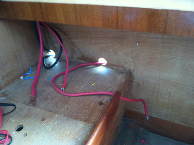
A cabin light with red and white light will go where the wires are dangling.


Sunday, September 1, 2013

ReWire the Boat

Yesterday, I began the total re-wire of the boat, starting with the DC system.  With the help of my friend, we accomplished quite a bit. Thanks Daniel!  

The biggest decision I had been toiling with was where to place the batteries.  When I bought the boat, I noticed the unused space in the stern.  I thought this would make a great place for the batteries, since there would not be any need to access them that often. However, two things got me to reconsider this location.  One, the extra weight aft was a concern, and Two, the longer distance away from all of the high usage items required higher gauge wire, especially if I decided to add a windlass.  I already bought all of the wire, so that was not as big of a concern, but it just made sense to put the batteries closer to the electrical panel, so............


In the cockpit lazzerette, they go!  I did also consider putting them in the storage area below the nav. table, but the batteries were just a bit to tall.  I will build a tray to put on top so I can still salvage some storage area and keep water off of the batteries.

As you can see, I am going with 2 - 6V Trojan deep cycle batteries combined in series for the 12V House and a Group 24 75Ah deep cycle battery for the Starter.

If I follow my previous boat, I will use the House to start the outboards as well and the Starter battery will just be used as emergency back up.

The cables run through the bulkhead to the inside of the cabin.


This will be built out to house the 1-2-Both battery switch.  My thought now is to place the inverter/charger to the right.  The ground wires go up to behind the cabinet.......


.....to the ground bus bar.

You can see from the ground bus bar that I went with yellow ground wire. Only the battery ground and the ground that goes to the fridge is black.

Here is the backside of my panel.  It is an 8 switch panel.  Wish I had one more switch! I only have one more wire to run and then the wires will get more tidy with zip ties.


Here is the panel from the front.  It looks lonely now, but it will be accompanied later by the battery monitors, inverter/charger monitor, LPG monitor, VHF radio, and stereo.


Here is the majority of the wiring leaving the panel.  The duplex wires are for the fridge and head.  They are 8 GA., which is now a bit over sized considering I moved the battery closer.

I may need to build up this area since I still need to run my VHF antennae, wind transducer, and radar. cable here as well.


Turning the corner.  Some wires have dropped off to feed the starboard side of the boat.  You can barely make out the starboard nav and cabin wiring in the below corner.


Here is a close up of that area.  I have left some wires loose so I can pigtail a cabin light in this area.  I was able to use the existing electrical chase in some cases.


Going to port, more wires drop off to go up the mast.  I will place a terminal strip in this enclosure for the wires going up the mast for the anchor, steaming, and deck lights.


Here is a shot from the other side.  I will likely place a puck light here to shine down on the settee table.


This next week, I hope to complete the DC and AC system, finish placing headliner material and start on the ceiling treatment.  After that, major projects left will be the plumbing and new floors.