Monday, February 4, 2013

Odd and Ends

I am trying to find some direction.  I still have plenty of fixing and fairing to do.  I am thinking that I will put down a prime coat on all of the new fiberglass in March and then follow shortly with the paint.  Until then I need to start contemplating the plumbing and electrical.  I have most if not all of the parts and pieces necessary.  I have another short week after Presidents day and will likely take that week off, pending decent weather.  Until then, here are a few more pictures of some of the odds and ends I have been working on.


Here is the hull extension join area that showed a poor join by the factory.


And here is a shot of the same area after sanding.  I could still feel a depression, so I took a straight edge and marked the larger area to place more fairing mix.


These are the 2 thru hull locations at the bathroom that I filled in and faired and sanded twice.  Its is ready for some primer.


If you remember, I bought 2 stern rails a few months back.  I decided to start dry fitting them.  My first concern was that they would conflict with the back stays.  I don't have a picture, but the back stay passes between the upper and middle rail...Whew!

I also need to straighten that existing stanchion shown on the left.  It leans forward and I want it to stand straight.


The bases on the new stern rail were obviously made for a different boat, so I am in the process of installing a spacer to take up the angle.  I will place some fiberglass mat and fiberglass it to the deck.  Just enough space to allow drainage on the left and clearance for the hatch cover on the right.


Here is the most aft stanchion base.  I ended up using a piece of the cabin top that I cut off.  The balsa was easy to cut and sand into the shape I needed.

After I fiberglass, prime and paint, I will drill holes straight through and secure with SS bolt, washer and nut.


Here is a shot of the starboard stern after I removed the teak rub rail.  The rub rail was modified to accept the davits that I will no longer use.  It is hard to see here, but there were lots of cracks on the top, so gouged out material at each crack in order to place some fairing mix and smooth out the whole area.  I will not likely replace a rub rail on the stern.  No real purpose other than looks, which had I been able to salvage it, I would have put it back.   I was able to salvage the rub rail on the inside  hull to the left and will reinstall in conjunction with a new swim step.


The port side fared much better, but will still need some attention to make this look nice.

Lots of little things!


Update: February 8, 2013

Raining again today, so I decided to start painting the berth storage areas.
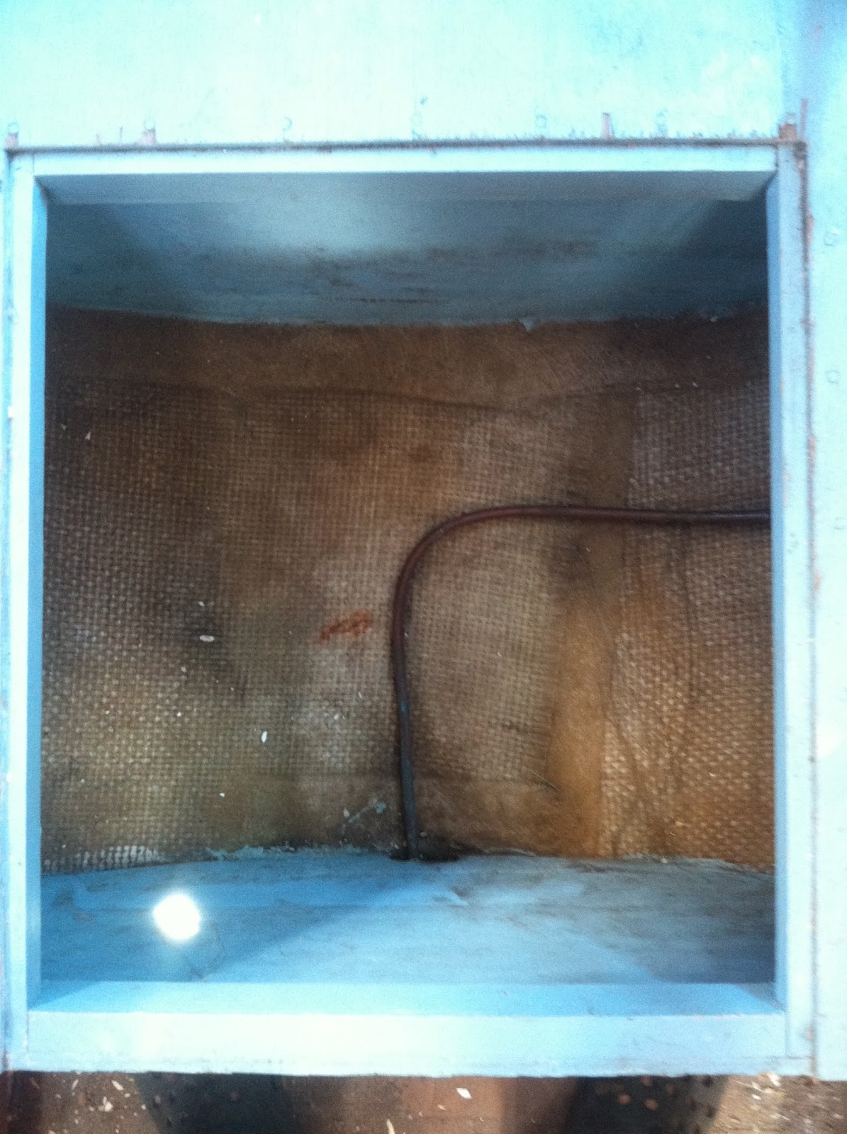

Here is the aft starboard berth storage area.  The copper pipe is the lpg supply to the stove.


BEFORE


I will be putting a 9 gallon HDPE water tank in here for the galley sink.  Looks more sanitary now doesn't it?


                                                             AFTER


It is amazing what a coat of paint can do for the psyche.  Just a small taste of what is to come!


Tuesday, January 22, 2013

Steering Mechanism - Part 2

I was off yesterday (MLK) and this Friday is my flex friday, so I decided to take the next 3 days off and work on the boat since rain is forecast for the weekend.  Made some more progress on the steering mechanism.


Here is the temporary steering arm attached to the rudder casing.  Notice the tiller has been chopped off.  No more deck sweeper.  I will likely fabricate something so that I can attach an aluminum pole as an emergency tiller.


Steering arm poking through the slot.


Next three shot of different position.  The part holding the teleflex cable came with the boat.  The arm connecting the cable to the steering arm was purchased at Minneys for $10.


LEFT


MIDDLE


RIGHT

It works!   Now to do the other side and buy some stainless steel angle iron to fabricate the real thing.  Not going to buy the square tube.  Too much cutting.

Monday, January 21, 2013

Steering Mechanism - Part 1

I moved the steering part from yesterday's blog post to this one for consistency and to match the title.


Working in Parallel.  I am always thinking ahead to the next project and surfing eBay for parts.  In the last week, I have purchased the 2 Teleflex steering cables.  One is 22' and the other is 15'.


Here is the 22' cable, which is for the port side,  dry fit on the rotary helm.    The 15' cable is in the mail.

I bought them from 2 different people and paid about $130 total, including shipping, which is about the cost of just the 15 foot one had I paid retail.


Both cables as well as the outboard cables, and wiring will all be run in the starboard berth area.


I am now contemplating where to create a chase for all of that.  One option is to create a chase here and cover it with the new ceiling.


The other option is under this sofit.  You can see where the existing wires run, but this will not be big enough for all of my electrical, since I will be also running large gauge wire from my battery to the electrical panel here as well.  This location might present a slight conflict with the new Bomar port light when I raise the "glass".


I have been contemplating my linkage from the steering cable to the rudder.  This past week I was rummaging through the stainless steel remnants/parts at Minney's.


I have no idea what these are, but I saw a possible steering arm for the rudder and the price was right $2.95 for the pair!


My plan is to cut off the excess to the left of the arrow.  The flange at the bottom right of the picture, will be connected to the rudder.

The flange is not currently at 90 degrees, so it will need to be bent.


The portion to the right of the flange will fit through a slot that I will cut in the transom and will be connected to the steering cable linkage.

The thickness of the arm is a little thinner than what I imagined, but I think it has the right bends in it to reinforce it in the right places.


What do they say about the best laid plans?  Today I decided to dry fit the arm to the rudder.  Doh!  not long enough.

Oh well maybe I will find another use for these parts.


On to Plan "B".  This is a 2" piece of aluminum square tube that I initially was going to use before I found the other parts at Minneys.  I decided to use aluminum to make sure Plan "B" works and if it does, then I will use a piece of stainless steel tube.

Laid out the pattern.


I was able to cut out the 2 arms from the same piece of square tube!


I am going to locate the steering arm vertically between the 2 hinges.  Now to mark the location of the slot.


I think that should do it.


Used a circular saw to cut out the initial slot.


This shot is taken from the other side.  As you can see, the slot protrudes into the backing plate for the rudder, but it is in the middle of the backing plate, and does not go all the way through, so should be just fine.


To Be Continued.......

Sunday, January 20, 2013

Fairing and More Fairing

This is the part of the restoration that I have dreaded.  Since the last post, I have been fairing and sanding the fiberglass that was not "form"-able.  I am getting close, maybe one more day and then I think it will be good enough for my primer.  I am eventually going to go with Interlux Epoxy Primekote.


Most of the pictures were taken today after various stages of fairing and sanding.  This one was taken a few days ago.


I will let the pictures speak for themselves!


This has been done for quite a while.  I really think the prime coat will help me see the defects better for the final fairing.


I placed a few layers of fabric and mat and closed up 2 thru hull holes from the bathroom.  I think one was for a manual bilge pump and the other, I don't recall.  I will be replacing the manual bilge with an automatic pump, but the thru hull will be placed on the inner side of the hull.


The factory did a poor job of joining the lengthened hull.  I am going to attempt to hide it, because it will likely show up like a sore thumb with my Navy Blue color scheme.


and one final coat on the slot reinforcement area.


Wednesday, January 2, 2013

Centerboard Slot Reinforcement

Okay, I think this will be one of the last major structural projects that I will undertake!  As suggested by Sailcraft, I decided to reinforce the centerboard (sideboard) slots.


Here is Sailcraft's recommendation.  Basically 3 layers of 1.5 oz mat and 3 layers of 12 oz fabric.  I had 7 oz, so that is what I used.  I ended up adding an additional layer of each for good measure.


The recommendation is to use an 8" radial layout.  I followed Jim Barton's (Martes) lead and just opted to make it 16" square.  Its just easier to cut the fabric.

This shot is my first test with the angle sander.  The disc is 60 grit I believe and is made for metal.  It worked great.


Here is the finished product.  This was my first time at this and I ended up with a couple of gouges, but that's okay.


This is a different location, but I wanted show what I think was a previous repair.  I am pretty sure that there was no gel coat over the brown area (fiberglass).


Before I started, I cut out all of the fabric and mat.  4 layers of each, starting at 16"x 16" square and ending at 9"x 9" square.

I used 16 oz of resin for each layup and was able to complete in one session before the resin started to kick in.


And the finished product after layup. Forward location.


And Aft.


Close up of the fabric over the slot opening.  I pushed the fabric up into the slot as best I could.


And after I cut out the fabric with my angle grinder and cutting wheel.   Used my multi function tool to cut the end.


I will probably sand it tomorrow and either cover with resin or fairing mix.

UPDATE: 1/12/13


Sanded and added first course of fairing mix.  Perhaps one more light sand and then a bit more fairing mix, especially around the edges.


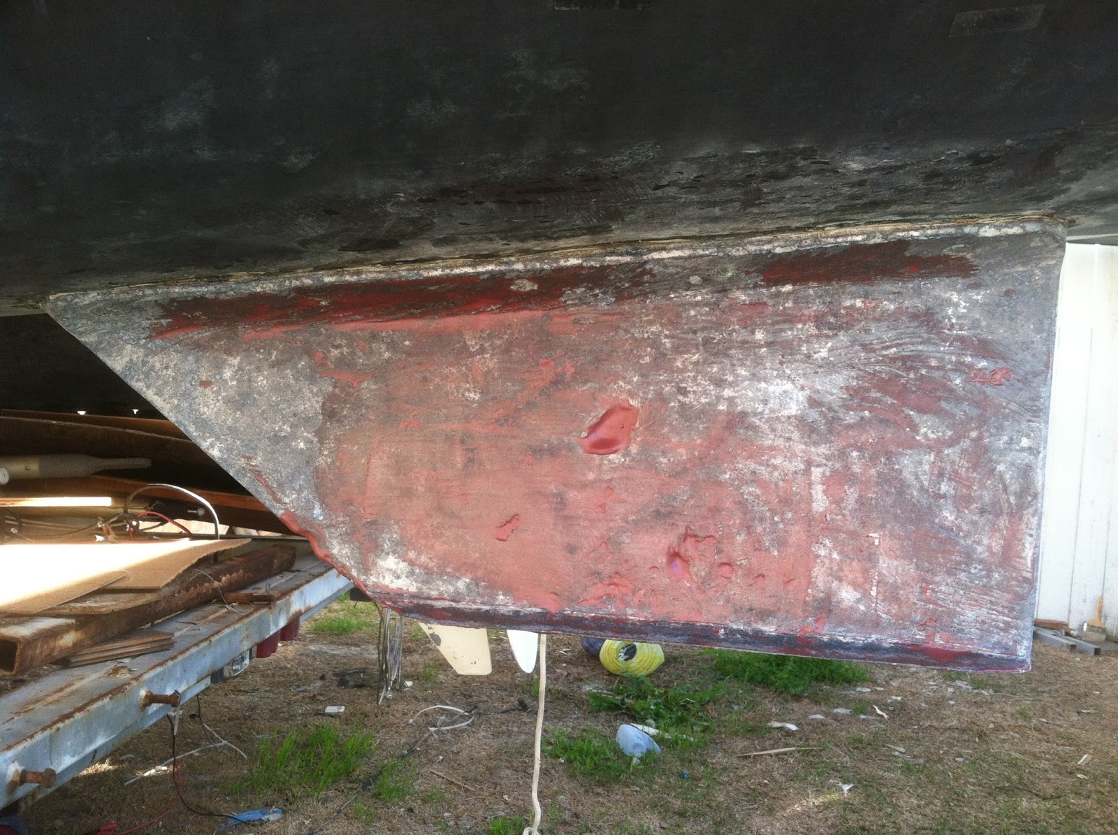
While I had my angle sander out, I decided to clean up the skegs.  


There was a remnant of the zinc still on the skeg.  I had to use my grinder to cut off the screws in order to remove the zinc.

The skegs were just crusty so I wanted to clean them up before I painted them.


This is after I sanded it down.  It looks like the moon surface with craters and pock marks.  I want to fill those in to smooth it out.  Not sure what to use, JB Weld, thickened epoxy?  I will post on Yahoo Group and see if I can get some recommendations.


UPDATE: 1/12/13


I had some fairing mix left over from the centerboards slot reinforcement so I used it on the skegs.  It was a little too runny so I will just make one more pass.


I think I have put off the fairing long enough.  I will likely start on the raised cabin and work my way down from there.  Probably start tomorrow.  Friday, I will be taking my Ericson out for a sail.  Yeah!