Sunday, December 29, 2013

Mast Lowered

I took off Christmas week and got a few things done.


I purchased a halyard organizer/mast plate from Garhauer.  My intent was to install it below the mast base.  After removing the 4 bolts that hold the mast base down, there was still something preventing me from removing it.  I am guessing there is some sort of attachment below in the cabin, but I did not want to tear up the woodwork.  So I just cut a hole in the organizer, placed it on top and secured it with the same 4 bolts.


I also installed the winches.  This is the port side showing the winch for the head sail sheets.  Forward is a deck organizer for the head sail halyards, so I can lead them aft and use the same winch.


This is the starboard side.  the Enkes 16 2-speed winch on the left will be for the main sheet, downhaul, topping lift, and main halyard.  Forward is the double stacked deck organizer.  The clutches in the picture have not been installed yet.  I will set them in place after I tie some mock lines from the halyard organizer and through the deck organizer.


This is near the base of the mast.  I will be running the halyards inside the most, so I cut holes for the exit plates.  The one exit plate shown is for the electrical loom.  The existing wires are shown running out of the middle exit plate hole.  They are somehow secured inside the mast as I can not pull them out!  Need to figure that one out.


Here is the loom laid out. It includes the wires for the anchor light, steaming light and deck lights, as well as the VHF antenna, wind transducer and WIFI antenna.


I used zip ties with a bit of room for ease of pulling any wire out if necessary. Used a bit of tape to keep the zip tie in place. Today, I tried to pull the loom through the mast, but was blocked by something.  I hope I don't have to run the wires individually as I am trying to keep thing inside the mast neat, since I will be running 4 halyards inside as well.


I also was able to squeeze in some finish work on the plumbing in the galley as well as run some more 110V wiring to the galley area.  I also ran wiring to the galley area bilge pump and to the area behind the refrigerator to feed the condenser and a wash down pump.  Forgot to take pictures of that though.  Maybe next post.

Happy New Year!


Sunday, December 15, 2013

Plumbing Continued

Wrapping up the plumbing and thru-hull installation.


This is the bronze 3/4" raw water intake with "screen" and 1 1/2" outlet for the head.


This is the other side showing the sea-cocks and backing blocks.


This is the 3/4" intake that was originally installed for the water cooled refrigerator.  It will be used to provide sea-water for the galley sink and also for a wash down pump.


And the other side, showing the sea-cock and the new thru-hull for the tri-ducer.


This is the tri-ducer thru hull with the plug installed.


Starting to look like a sea monster!  Starting from the right.  1 1/2" waste outlet.   From the 3/4" intake the raw water will travel up through a screen filter and up to an anti-siphon then down to a 3-way valve that will direct either raw water or gray water to the toilet.


Close up of the anti-siphon valve.  It has a solenoid installed to keep the intake primed.  Also shown is the 1 1/2" discharge tube that goes to the waste tank.  Since the waste tank is above the water line, there is no need for an anti-siphon valve.


A better shot of the 3-way valve for the toilet supply.  I need another NPT to barb fitting to make the connection.  Note the arrows!


This piece of plywood will provide support for the toilet. I put several coats of polyurethane on all sides to water proof it.


This is my Jabsco Lite Flush electric toilet, temporarily placed to make sure everything is properly placed.  I will place a facade in front of the waste tank and also try to place a piece below the shelf to hide the mechanics below while still providing access to the valves.


This is just a picture of the bilge pump that will be installed in the galley. Trying to place any wiring and tubing prior to installing the sole.


Speaking of which, I temporarily installed the sole to check out the fit.  Starting to come together.


I also temporarily installed the main cabin sole.  The sole was a bit bouncy under foot.  Not acceptable.  I realized that the fiberglass beneath is not even.


There is a distinct depression in the middle.  I am applying some floor patch to even it out.


Pretty fruitful weekend.


Sunday, December 8, 2013

Head Plumbing

Rain on Saturday put a damper on my progress, however today I have made a little more progress on the head plumbing and a couple of other things.


I fiberglassed the backing blocks for the seacocks today.  The Thru-hulls are dry fit in place, but I will remove them to paint the blocks.  I ended up using some scrap Mohagany wood I had for the blocks.  I will just use screws to secure the seacocks to the blocks.


This photo shows the 3-way valve that I mounted underneath the waste tank shelf.


This photo shows that the 3-way valve is about one to two inches above the waterline.  The waterline mark shown is even with the bottom of the boot stripe.


This is an overhead shot showing the submersible pump. It has a 3/4" discharge that will run to under the sink. You can also see the 1/2"  feed teed of to go up to the sink.  The other white 3/4" will provide gray water from the pump or potable water from the sink to the toilet as an option to the seawater intake.


This is another side project.  I added an access hatch to the bulkhead that is between the starboard forward locker and the single berth area.  The previous owner installed a freezer/refrigerator to the berth area, which created some unusable space behind it.  This hatch will allow me to access that area.


This is the space accessible by the hatch. My plan now is to locate the condenser here instead of the storage area beneath the berth.  I also considering adding a wash down pump and locating it here as well.


This is just an updated photo of the progress on my sole.  I have one small area that needs pin striping.  14 coats of poly on the main cabin sole and 7 coats on the other pieces.  More coats to come.


More to come.

Wednesday, November 27, 2013

More Sole and a Little Plumbing & Electrical

Since I have this whole week off, I have made some good progress as of today, so I decided to update the Blog.


On Saturday, I stained the plywood.  I ended up letting the first coat dry. There were some spots where the grain was too noticeable across a wide area, so in order to try an replicate individual planks, I added another coat. This time, I used a crumbled piece of paper towel and pulled the stain to try and add some linear effects. I think I like it okay.

This photo is of the sole for the port an starboard hulls, except for the small piece at the top.  It is the piece that will go just starboard of the main cabin sole, leading to the starboard hull.


This is the main cabin sole.

On Saturday and Sunday, I added 4 coats of polyurethane to the back and sides of all of the pieces.


This is my test piece to see how the poly would look.  My biggest concern was that the pin stripe would stay white.  The poly is oil based and after 4 coats, the pin stripe is discernibly yellowish, which is what I wanted, although this photo does not show it.


Monday morning, I sanded all of the pieces with a 400 grit sandpaper and started applying the pin striping.  I ordered 150 feet of pin striping. After finishing the main cabin sole, pictured, it was obvious that I would not have enough pin striping for the rest of the pieces. It took me over an hour to lay these down.  I got about half way through with the sole that goes below the settee, when I ran out of pin striping! This screwed up my whole game plan for the sole.

Because, I am using oil-based poly, you can only do 2 coats in a day.  Right now I have it timed to coat at 7:00 am and 4:00 pm. This gives the recommended 8-10 hours of dry time between coats, but does not need to be sanded, because its 15 hours or less between the 2nd coat of the day and the 1st coat the next morning.


This is after 5 coats of semi-gloss poly, which I think I am going to stick with to offset the rest of the wood in the cabin, which is gloss.  I am going to do 5 more coats over the next few days.  I will have to wait until Christmas week to poly the remaining pieces.


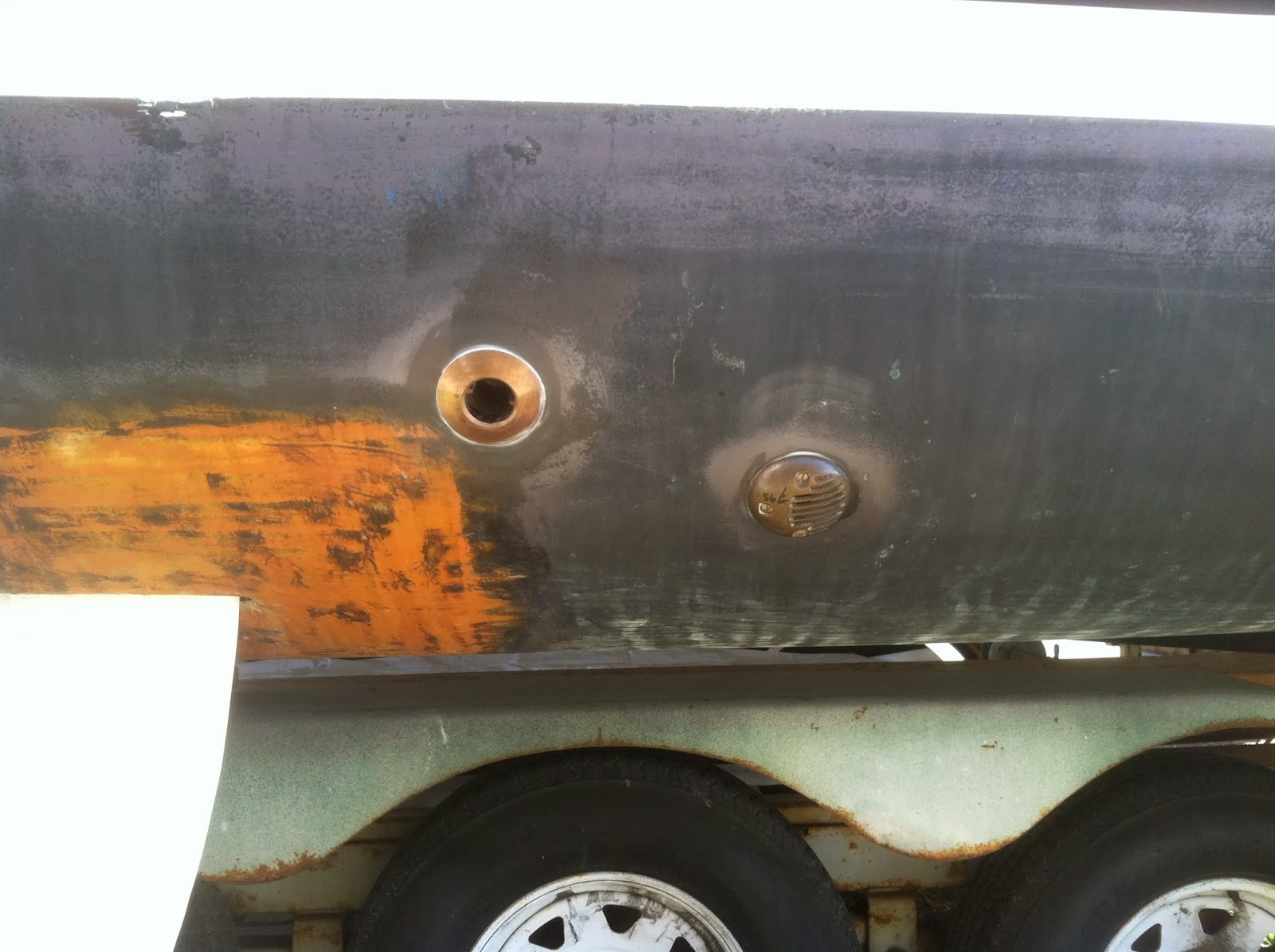
While, the poly was drying, I started the plumbing. This photo shows the new location of the water fill.  There is one similar on the starboard side as well.  I know Iroquois were built primarily as racers, but this location just seems a lot more appropriate.


This is the water tank in the port forward berth area. It will primarily be empty and used as a secondary tank for trips to Catalina.  There is no deck fill tube.   I will open the valve and let the water equalize as I fill the primary tank and then close the valve until I need the water.  That way I have a reserve.  I just need to add an air relief vent.


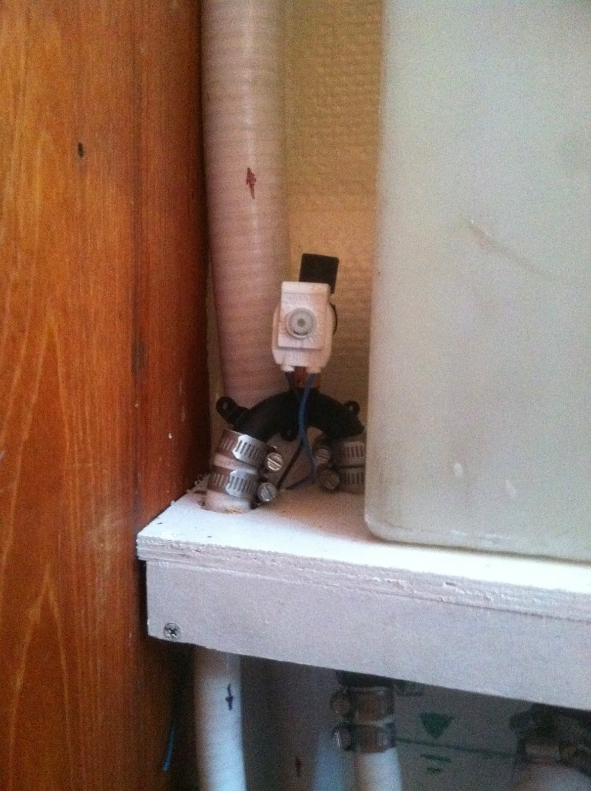
This photo shows the 1/2" tube connection running from forward to aft tanks.  I will tee off of this tube to supply water for the head sink.  I will be reusing the pump that was installed by the PO, so I can have a hand shower.  At this point, I think that I will put the bilge pump in the recessed area in the head.

This photo also shows some added stingers to better support the sole.  I still may need to double up on the plywood, but that is okay, I have enough left over.


I also started building the support for the waste tank. The ledgers on the bottom will support the 3/8" plywood floor for the tank.  I will add a strip of plywood to the floor to give it some rigidity.  I also have a piece of aluminum tubing that will also add to bridge fore and aft.

The top piece is to provide a place to strap the top of the tank.


Today, I tabbed in the ledgers.  The piece on the left is screwed into the wall with a backing strip on the other side, which is in the berth cabinet.  The top strip, not shown, also got tabbed in as well.


Here is a shot with the tank in place. The 1.5" intake is upper aft. The tube, top forward will be used for the air vent.  There is a 1.5" port on the bottom right.  This will eventually all get closed in with a removable face, once all of the plumbing is complete.

The tank was another Minney's purchase for $18 and I estimate is about 9 gallons.  I was looking at a new tank, which was going to cost over $100.


In anticipation of laying down the cabin sole, I decided to run the electrical/wiring.  This photo is looking aft toward the electrical cabinet. On the left is the starboard bilge hot wire and a duplex wire for the refrigerator.  I am just going to use the ground from the duplex for the bilge, since is oversized.  I also ran the cable for the tri-ducer and depth transducer.

On the right is the 110V romex that will feed power to the forward part of the hulls.


This photo is looking forward, under the settee table. The wires/cables run inside the cubby and through the settee seats to the corresponding hulls.  I think I am also going to add some pull lines before I put the sole down to make it easier to add more wires in the future.


This shot is in the starboard hull, near the forward berth, showing the wires coming out and down into the locker. I am going to put a (+) and (-) bus here.  The duplex is 8 ga. and the refrigerator takes 10 ga..  I was originally going to put the buses in the locker, but both electrical wires came up short.  This was not my original path of travel, when I cut the wires a few months ago.  I will eventually cover this gap between the cubby and the refrigerator so you don't see the wires.


This is a shot of the transducer wires leading into the locker.  I discovered that the thru hull from the previous depth ducer was not compatible with the new triducer. If you are following closely, you are wondering why I have a tri-ducer (depth, speed, temperature) and a separate depth transducer.  The Raymarine depth and speed gauges I purchased are older ST60 and so the triducer was purchased to be compatible.  I also purchased a Raymarine DSM 250 Depth/Sonar to feed to the Raymarine Chartplotter.  Since I am not sure if the triducer will provide the correct information, I went ahead and purchased a separate depth gauge that I know is compatible.  Not sure if I will need it, but just easier to install now. Plus the triducer is angled off to the side, so it will be interesting to see how accurate a depth it reports.


This photo shows the 110V romex in the port forward cubby, coming from the settee area.  I will install an outlet here and continue the romex to the head.


This is the same cubby, taken a couple feet back.  The romex will be attached to the shelf above, so it will not be visible.


The romex will then be attached under the top step and into the head.


Its been a busy few days.  Celebrating Thanksgiving tomorrow, but I will still get my 2 coats of poly done!


Wednesday, November 20, 2013

Sole Prep Continued

Decided to make some progress on the sole.  The polyurethane I have has a 6 hour dry time between coats, so it makes sense to get that started while I work on other things.  I have the week of Thanksgiving off, so that is when I am likely to start the coating process.


This is the template I created for the main salon sole.  I am going to attempt to lay as big a sheet of plywood as I can.  It will take some maneuvering to get passed the settee table and under the settee, but I think I can do it.


Here is the template in the port hull. I am going to add more stringers to help support the plywood sole.


I also decided to add more stringers to the depressed area to support the plywood.  To cut down on weight, I made a decision to go with 1/4" thick plywood.  The main salon is 4 feet wide plus the small area between the settee and the nav station, so there will be a joint there. Hopefully the plywood will be rigid enough to allow for a clean joint. Right now I am thinking of not using any adhesive on the plywood and simply using border base board to keep it down.  Time will tell if that will be sufficient.


Here is a shot of what the sandply (home depot) plywood looks like.  It has a very soft grain pattern, so hopefully it will not be too obvious after I lay down the pin stripes, that it is one piece of wood. This was $30 a sheet.  I anticipated using 3 sheets. In reality I ended up with 4 sheets since I did not take the time to lay out all of the templates at one time.  That is okay, two of the remnant sheets will allow me to double up on the thickness in the hull sections if needed, since I ripped out the existing sole leaving only the supporting "joists", I may need the extra stiffness.


Here is a close up of the plywood to show the grain pattern.  The 1/2" thick sandply had an even softer grain than this that I much prefer.

I was able to cut out all of the sections of the sole and they are now sitting waiting for stain and poly.


I dry fit the facade for the electrical chase in the starboard berth.  This should clean up nicely once I trim out the edges with some "L" molding.