Okay, I think this will be one of the last major structural projects that I will undertake! As suggested by Sailcraft, I decided to reinforce the centerboard (sideboard) slots.
Here is Sailcraft's recommendation. Basically 3 layers of 1.5 oz mat and 3 layers of 12 oz fabric. I had 7 oz, so that is what I used. I ended up adding an additional layer of each for good measure.
The recommendation is to use an 8" radial layout. I followed Jim Barton's (Martes) lead and just opted to make it 16" square. Its just easier to cut the fabric.
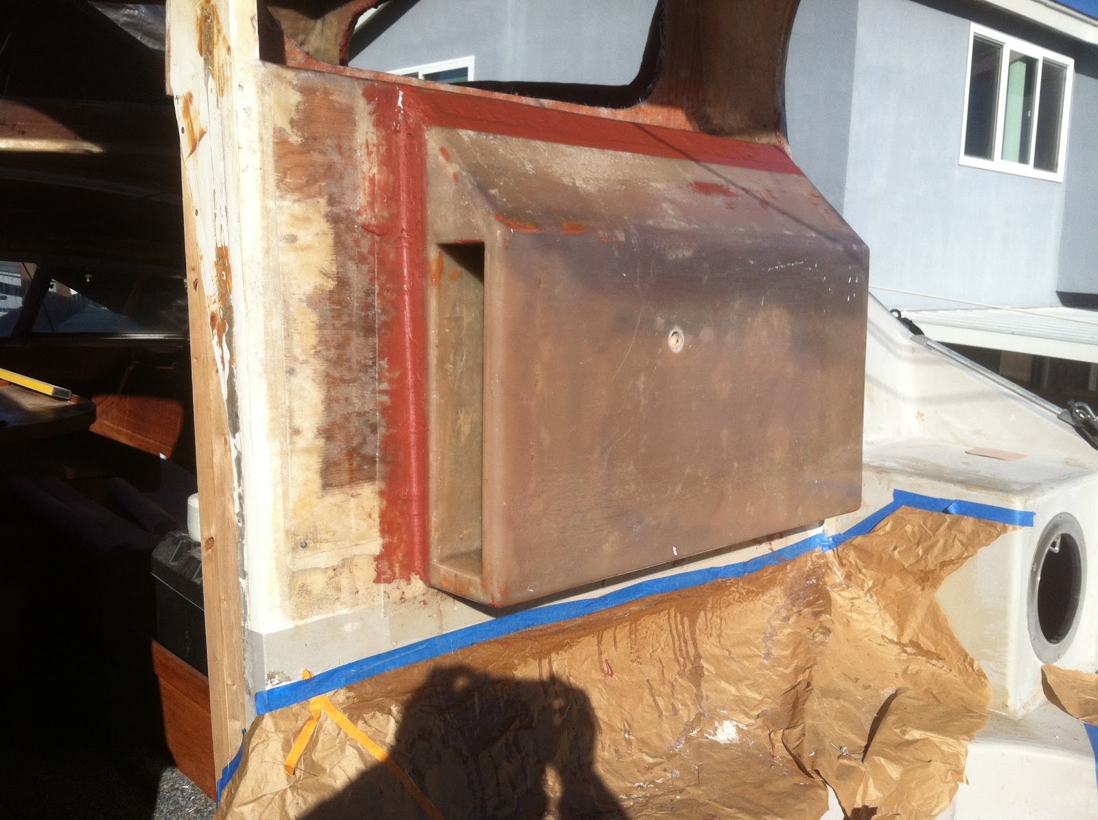
This shot is my first test with the angle sander. The disc is 60 grit I believe and is made for metal. It worked great.
Here is the finished product. This was my first time at this and I ended up with a couple of gouges, but that's okay.
This is a different location, but I wanted show what I think was a previous repair. I am pretty sure that there was no gel coat over the brown area (fiberglass).
Before I started, I cut out all of the fabric and mat. 4 layers of each, starting at 16"x 16" square and ending at 9"x 9" square.
I used 16 oz of resin for each layup and was able to complete in one session before the resin started to kick in.
And the finished product after layup. Forward location.
And Aft.
Close up of the fabric over the slot opening. I pushed the fabric up into the slot as best I could.
And after I cut out the fabric with my angle grinder and cutting wheel. Used my multi function tool to cut the end.
I will probably sand it tomorrow and either cover with resin or fairing mix.
UPDATE: 1/12/13
Sanded and added first course of fairing mix. Perhaps one more light sand and then a bit more fairing mix, especially around the edges.
While I had my angle sander out, I decided to clean up the skegs.
There was a remnant of the zinc still on the skeg. I had to use my grinder to cut off the screws in order to remove the zinc.
The skegs were just crusty so I wanted to clean them up before I painted them.
This is after I sanded it down. It looks like the moon surface with craters and pock marks. I want to fill those in to smooth it out. Not sure what to use, JB Weld, thickened epoxy? I will post on Yahoo Group and see if I can get some recommendations.
UPDATE: 1/12/13
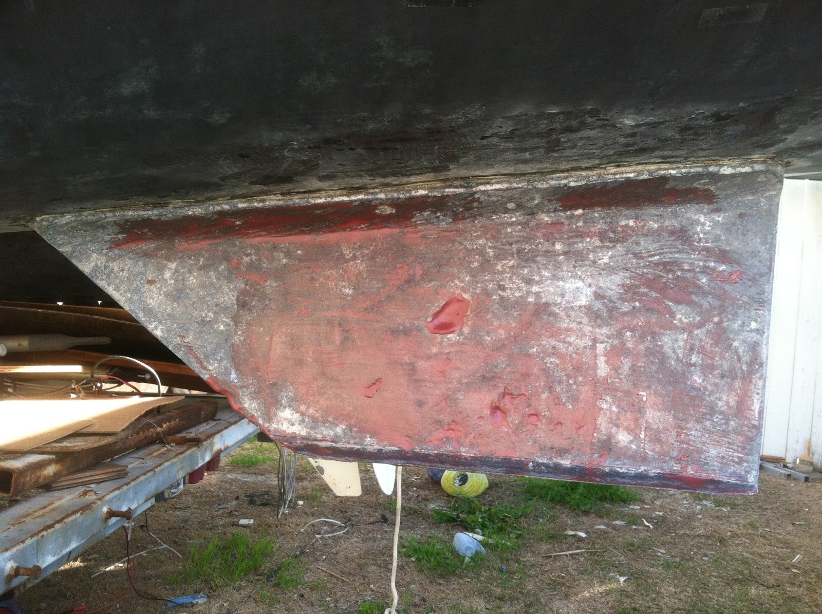
I had some fairing mix left over from the centerboards slot reinforcement so I used it on the skegs. It was a little too runny so I will just make one more pass.
I think I have put off the fairing long enough. I will likely start on the raised cabin and work my way down from there. Probably start tomorrow. Friday, I will be taking my Ericson out for a sail. Yeah!
Wednesday, January 2, 2013
Sunday, December 30, 2012
The Mast is Risen
Well I decided to raise the mast to get it and all of the standing rigging out of the way so I could start the fairing and fiberglass repair on the cabin, deck and cockpit.
Once I started piecing all of the parts together, I started noticing things I was not too sure about.
This is one side of the boom with a large slot, likely to fit slugs on the foot of the sail. I can't remember if my sail has slugs or a rope foot. No need to worry, the other side of the boom has a smaller slot, that looks like it will accommodate a rope footed sail.
The next puzzle. This is a shot near the chain plate for the shrouds. There is an outer shroud that attaches at the top of the mast and an inner shroud that attaches just below the spreader. What was confusing is that there was what appeared to me at first to be a 3rd shroud also attached just below the spreader. It had a block on the other end of it. After doing some "asking", I now believe it to be a running back stay. I learned something new.
After studying the "How to raise the mast" drawing put out by Sailcraft, I was successful in getting it done with the help of my son and one of his friends. Was able to do it without a winch. I just used a 6:1 purchase and the 3 of us pulled it up quite easily. We just beat another shower, in fact we had pea size hail!
A shot from the front.
and a closeup (blurry) shot to show the clearance between the cabin roof and the boom. About 3 inches here.
At this level, the goose neck attachment is about 2 to 3 inches below the track opening where the sail slugs enter the mast track. Time will tell if I need to modify the main sail.
By the way, yesterday, this blog had exceeded the 2000 page view mark. Incredible!
Once I started piecing all of the parts together, I started noticing things I was not too sure about.
This is one side of the boom with a large slot, likely to fit slugs on the foot of the sail. I can't remember if my sail has slugs or a rope foot. No need to worry, the other side of the boom has a smaller slot, that looks like it will accommodate a rope footed sail.
The next puzzle. This is a shot near the chain plate for the shrouds. There is an outer shroud that attaches at the top of the mast and an inner shroud that attaches just below the spreader. What was confusing is that there was what appeared to me at first to be a 3rd shroud also attached just below the spreader. It had a block on the other end of it. After doing some "asking", I now believe it to be a running back stay. I learned something new.
After studying the "How to raise the mast" drawing put out by Sailcraft, I was successful in getting it done with the help of my son and one of his friends. Was able to do it without a winch. I just used a 6:1 purchase and the 3 of us pulled it up quite easily. We just beat another shower, in fact we had pea size hail!
A shot from the front.
and a closeup (blurry) shot to show the clearance between the cabin roof and the boom. About 3 inches here.
At this level, the goose neck attachment is about 2 to 3 inches below the track opening where the sail slugs enter the mast track. Time will tell if I need to modify the main sail.
By the way, yesterday, this blog had exceeded the 2000 page view mark. Incredible!
Thursday, December 27, 2012
Helm Station - Part 3
This past weekend was a bust, down with the flu. Well enough to enjoy Christmas though. Got back at it yesterday.
I tabbed in the helm and finished fiberglassing the remainder of the bulkhead. I think that completes my major fiberglass projects. Likely some additional small fiberglass work in my future to close relocated thru hulls etc.
Oh yeah and I want to reinforce the drop board casings. Maybe that might happen in the next few days.
This is just a shot I took this morning. I like the lines of the raised roof from this angle.
Started mocking up the placement of the wheel and controls. I need to measure for my steering and outboard control cables.
My first layer of fairing mix.
I tabbed in the helm and finished fiberglassing the remainder of the bulkhead. I think that completes my major fiberglass projects. Likely some additional small fiberglass work in my future to close relocated thru hulls etc.
Oh yeah and I want to reinforce the drop board casings. Maybe that might happen in the next few days.
This is just a shot I took this morning. I like the lines of the raised roof from this angle.
Started mocking up the placement of the wheel and controls. I need to measure for my steering and outboard control cables.
My first layer of fairing mix.
Sunday, December 16, 2012
Helm Station - Part 2
Who says it never rains in California? The past 2 weekends have not been conducive to working outside, but I managed to make some progress.
Here is the helm station out of the mold. I spent about an hour sanding off remnants of the mold. Instead of using melamine, I used pieces of 2 doors from IKEA that we were going to throw away. The white surface of the IKEA doors are basically shrink wrapped onto the particle board.
Unfortunately, the cohesion between the fiberglass and the shrink wrapped material was greater and the stuff just peeled off the particle board in some spots.
A shot from the starboard side. You can see a void smack dab in the middle of the front surface. I drilled a small hole and applied a layer of resin along the entire surface.
Here is the back. I fiberglassed in 3/4" plywood on the top and front for structure and to accommodate the rotary helm mechanism.
I had enough time today to mount the helm station to the bulkhead. I had prior cut out a piece of the plywood bulkhead and actually used it for the helm structure. This cubby will be for a fire extinguisher.
I decided to mount the helm station off center, because my idea is to place the helm chair as far starboard as I can. That way I can easily see either through the cabin or along the starboard side of the cabin roof. You can revert back to my drawing I posted in a previous Post.
A shot from the starboard side. The cubby will be for my winch handle(s). This is a good time to comment on an Oh Oh moment I had right after laying the last layer of mat in the form a few days ago.
The form was made perfectly square. I realized that the bulkhead was angled forward. Since I did not want the helm station to conform to this angle, I used the plywood to take up the difference. In the long run, this works out nicely since now I have a place to tab when I fiberglass the helm station to the bulkhead.
Just making lemonade!
You can see the remnants of the shrink wrap material in the cubby. I decided to just add a thin layer of resin on top instead of trying to sand it off by hand.
BTW, the lid in the bottom of the picture can be fully raised vertical, without hitting the helm station.
Obviously all plywood used in this project needs to be fiberglassed when exposed to the elements. I had purposely left the plywood on the bulkhead un-fiberglassed until after I mounted the helm station. You can see from this picture that I will have a nice overlap of mat/fabric when I fiberglass this area.
You would think I knew what I was doing!
Another shot of the port side to show the angle of the bulkhead.
Off to the right of the picture, you can see my continuing efforts with making a filler mix of resin to fill in the hole in the gunwal left by the old controls. I think I am finally getting it. Used a mix of resin, micro balloons and cabosil. Actually you can also see it on various spots of the helm station where there were mold defects.
These next two pictures are from the inside of the cabin to try and show the cavity that will house all of the helm mechanics and electronics.
You can see the screws at the top and right hand side of the picture that I used to mount the helm station.
Have not really decided on the configuration of the wall to hide all of this stuff. I am likely going to build a wall just aft of the nav table. I will place an access door as well as the electrical panel. In fact, I may just have the majority of the wall be the door so I can flip it down to access either the helm station mechanics or the back of the electrical panel. I guess I will decide how far forward the wall will be once I install all of the gadgets and gismos!
I will be taking 2 weeks off for Christmas, so hopefully I will be able to make some good progress toward the steering and outboard controls. That should complete the major structural modifications, then it will be on to plumbing and electrical. I will likely tackle plumbing first since that will account for any more holes that need to be made.
Here is the helm station out of the mold. I spent about an hour sanding off remnants of the mold. Instead of using melamine, I used pieces of 2 doors from IKEA that we were going to throw away. The white surface of the IKEA doors are basically shrink wrapped onto the particle board.
Unfortunately, the cohesion between the fiberglass and the shrink wrapped material was greater and the stuff just peeled off the particle board in some spots.
A shot from the starboard side. You can see a void smack dab in the middle of the front surface. I drilled a small hole and applied a layer of resin along the entire surface.
Here is the back. I fiberglassed in 3/4" plywood on the top and front for structure and to accommodate the rotary helm mechanism.
I had enough time today to mount the helm station to the bulkhead. I had prior cut out a piece of the plywood bulkhead and actually used it for the helm structure. This cubby will be for a fire extinguisher.
I decided to mount the helm station off center, because my idea is to place the helm chair as far starboard as I can. That way I can easily see either through the cabin or along the starboard side of the cabin roof. You can revert back to my drawing I posted in a previous Post.
A shot from the starboard side. The cubby will be for my winch handle(s). This is a good time to comment on an Oh Oh moment I had right after laying the last layer of mat in the form a few days ago.
The form was made perfectly square. I realized that the bulkhead was angled forward. Since I did not want the helm station to conform to this angle, I used the plywood to take up the difference. In the long run, this works out nicely since now I have a place to tab when I fiberglass the helm station to the bulkhead.
Just making lemonade!
You can see the remnants of the shrink wrap material in the cubby. I decided to just add a thin layer of resin on top instead of trying to sand it off by hand.
BTW, the lid in the bottom of the picture can be fully raised vertical, without hitting the helm station.
Obviously all plywood used in this project needs to be fiberglassed when exposed to the elements. I had purposely left the plywood on the bulkhead un-fiberglassed until after I mounted the helm station. You can see from this picture that I will have a nice overlap of mat/fabric when I fiberglass this area.
You would think I knew what I was doing!
Another shot of the port side to show the angle of the bulkhead.
Off to the right of the picture, you can see my continuing efforts with making a filler mix of resin to fill in the hole in the gunwal left by the old controls. I think I am finally getting it. Used a mix of resin, micro balloons and cabosil. Actually you can also see it on various spots of the helm station where there were mold defects.
These next two pictures are from the inside of the cabin to try and show the cavity that will house all of the helm mechanics and electronics.
You can see the screws at the top and right hand side of the picture that I used to mount the helm station.
Have not really decided on the configuration of the wall to hide all of this stuff. I am likely going to build a wall just aft of the nav table. I will place an access door as well as the electrical panel. In fact, I may just have the majority of the wall be the door so I can flip it down to access either the helm station mechanics or the back of the electrical panel. I guess I will decide how far forward the wall will be once I install all of the gadgets and gismos!
I will be taking 2 weeks off for Christmas, so hopefully I will be able to make some good progress toward the steering and outboard controls. That should complete the major structural modifications, then it will be on to plumbing and electrical. I will likely tackle plumbing first since that will account for any more holes that need to be made.
Sunday, December 2, 2012
Helm Station - Part 1
This project will likely have several "Parts". Its been raining since Friday, but I have been able to squeeze in a little bit of work on the helm station.
This is the mold for the helm station. The 2 cubbies were afterthoughts. I had already assembled the main form and applied silicon fillets. The crevice between the cubbies and the forward part of the form presented a challenge in placing fillets and subsequently laying mat and fabric. I was able to apply a layer of each today, but got to dark to take a picture. I will need to apply one additional layer of mat and fabric, but since it gets dark around 5:00, it'll have to wait until next weekend.
The cubbies were sized to accommodate a fire extinguisher on the port side and one or two winch handles on the starboard side.
That is all for this post!
This is the mold for the helm station. The 2 cubbies were afterthoughts. I had already assembled the main form and applied silicon fillets. The crevice between the cubbies and the forward part of the form presented a challenge in placing fillets and subsequently laying mat and fabric. I was able to apply a layer of each today, but got to dark to take a picture. I will need to apply one additional layer of mat and fabric, but since it gets dark around 5:00, it'll have to wait until next weekend.
The cubbies were sized to accommodate a fire extinguisher on the port side and one or two winch handles on the starboard side.
That is all for this post!
Sunday, November 25, 2012
Let there be (Port) Light!
One of the downsides to the Iroquois are the "smallish" berths that without sufficient lighting could be claustrophobic I wanted to give it a bigger feel by letting in more light.
My first decision was to add port lights to the aft berths looking out onto the cockpit area. Cutting holes in a boat is always a cause for deliberation.
I decided to place it in the middle fore to aft. I used the back trim as the template for the cutout.
Unfortunately that was not right. I needed to use the actual port as a template. Fortunately it is bigger than the trim.
Just dry fit for now.
I also wanted to add port lights to the exterior. This required a little more thought as to what else I would put on the outside as well as the paint scheme. Here is a photoshop rendering of the paint scheme I want to go with. Dark Navy Blue with a gold pin stripe.
Sailcraft named their different model catamarans after different Indian nations, such as Iroquois, Comanche and Chieftan. To keep with the theme, I want to utilize the gold pin stripe and create an arrow. This is a condensed version:
The model of my catamaran is an Iroquois and the model is a MKIIA. The hull number is 235.
Besides the port lights, I want to relocate the navigation lights to the hull, so I am going with these new LED lights:
And these are the Port Lights.
I want the port lights and the navigation lights to line up with the gold pin stripe. I decided to locate the pin stripe 6" below the teak rub rail.
I decided to cut out some templates so I could play with their location.
Then I decided to go for it! Dry fit for now. I will permanently place them after I paint in a few months.
I like it!
I also decided to add port lights to the interior hulls.
There was not a lot of room to place these as it is just a few inches from the forward storage locker bulkhead.
Starboard Aft Berth area. Lots of light.
Port Aft Berth.
Port Forward Berth
Next weekend I will move onto fabricating the Helm area. Hopefully by the end of the year all of the major exterior modification will be in place
My first decision was to add port lights to the aft berths looking out onto the cockpit area. Cutting holes in a boat is always a cause for deliberation.
I decided to place it in the middle fore to aft. I used the back trim as the template for the cutout.
Unfortunately that was not right. I needed to use the actual port as a template. Fortunately it is bigger than the trim.
Just dry fit for now.
I also wanted to add port lights to the exterior. This required a little more thought as to what else I would put on the outside as well as the paint scheme. Here is a photoshop rendering of the paint scheme I want to go with. Dark Navy Blue with a gold pin stripe.
Sailcraft named their different model catamarans after different Indian nations, such as Iroquois, Comanche and Chieftan. To keep with the theme, I want to utilize the gold pin stripe and create an arrow. This is a condensed version:
The model of my catamaran is an Iroquois and the model is a MKIIA. The hull number is 235.
Besides the port lights, I want to relocate the navigation lights to the hull, so I am going with these new LED lights:
And these are the Port Lights.
I want the port lights and the navigation lights to line up with the gold pin stripe. I decided to locate the pin stripe 6" below the teak rub rail.
I decided to cut out some templates so I could play with their location.
Then I decided to go for it! Dry fit for now. I will permanently place them after I paint in a few months.
I like it!
I also decided to add port lights to the interior hulls.
There was not a lot of room to place these as it is just a few inches from the forward storage locker bulkhead.
Starboard Aft Berth area. Lots of light.
Port Aft Berth.
Port Forward Berth
Starboard Aft Berth area.
Next weekend I will move onto fabricating the Helm area. Hopefully by the end of the year all of the major exterior modification will be in place
Friday, November 23, 2012
Swell Guard
Don't really have any pictures, but earlier in the week I finished fiberglassing the cabin top by laying the final layer of fabric. Now I need to hone my skills in fairing.
In the mean time, I made progress on the "swell guard".
Here is a picture of the swell guard fresh out of the mold.
Use some marine plywood to give it some structural support.
Added a layer of fiberglass. There are 2 drain holes from the cockpit that will drain onto this and drain out the back, so I need to waterproof this.
Dry fit in place. Fits nice and snug so I will be able to screw it from above from the stern cavity without any assistance!
I need more resin. I have been through 3- 5 gallon pales of resin so far! One more should do it. The boat supply store where I get the vinylester resin was closed today, so for the next couple of days I might start cutting out the port windows in the cockpit and possibly the ones in the hull.
I also am waiting for the dual engine control to come in so I can start fabricating the mold for the helm station. That should be the last major fabrication.
In the mean time, I made progress on the "swell guard".
Here is a picture of the swell guard fresh out of the mold.
The other side.
Use some marine plywood to give it some structural support.
Added a layer of fiberglass. There are 2 drain holes from the cockpit that will drain onto this and drain out the back, so I need to waterproof this.
Dry fit in place. Fits nice and snug so I will be able to screw it from above from the stern cavity without any assistance!
I need more resin. I have been through 3- 5 gallon pales of resin so far! One more should do it. The boat supply store where I get the vinylester resin was closed today, so for the next couple of days I might start cutting out the port windows in the cockpit and possibly the ones in the hull.
I also am waiting for the dual engine control to come in so I can start fabricating the mold for the helm station. That should be the last major fabrication.
Subscribe to:
Posts (Atom)